dEZignLink for STAAD.Pro
Designed to help Structural Engineers work more efficiently with Bentley STAAD.Pro
Featuring a collection of carefully curated tools, this toolbar delivers exceptional time savings.
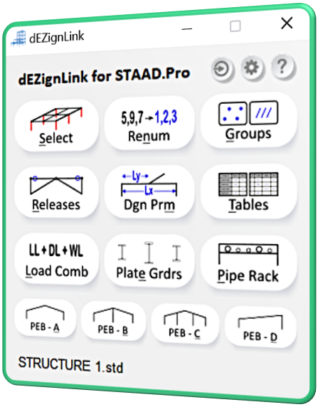
Key Features
- • Select specific element types auto-defined by dEZignLink
- • Renumber large structures effortlessly
- • Automatically create Groups for easy model controlling
- • Define Releases quickly and easily
- • Assign Design Parameters in just seconds
- • Generate essential Output Tables, along with pivot tables
- • Generate Load Case & Combination tables seamlessly
- • Create user-defined Plate Girders
- • Generate Structure Geometries in seconds
Enhance your workflow with dEZignLink and experience unmatched efficiency.
Installation
Downloaded the installer package from your account dashboard's Downloads section, as shown below:
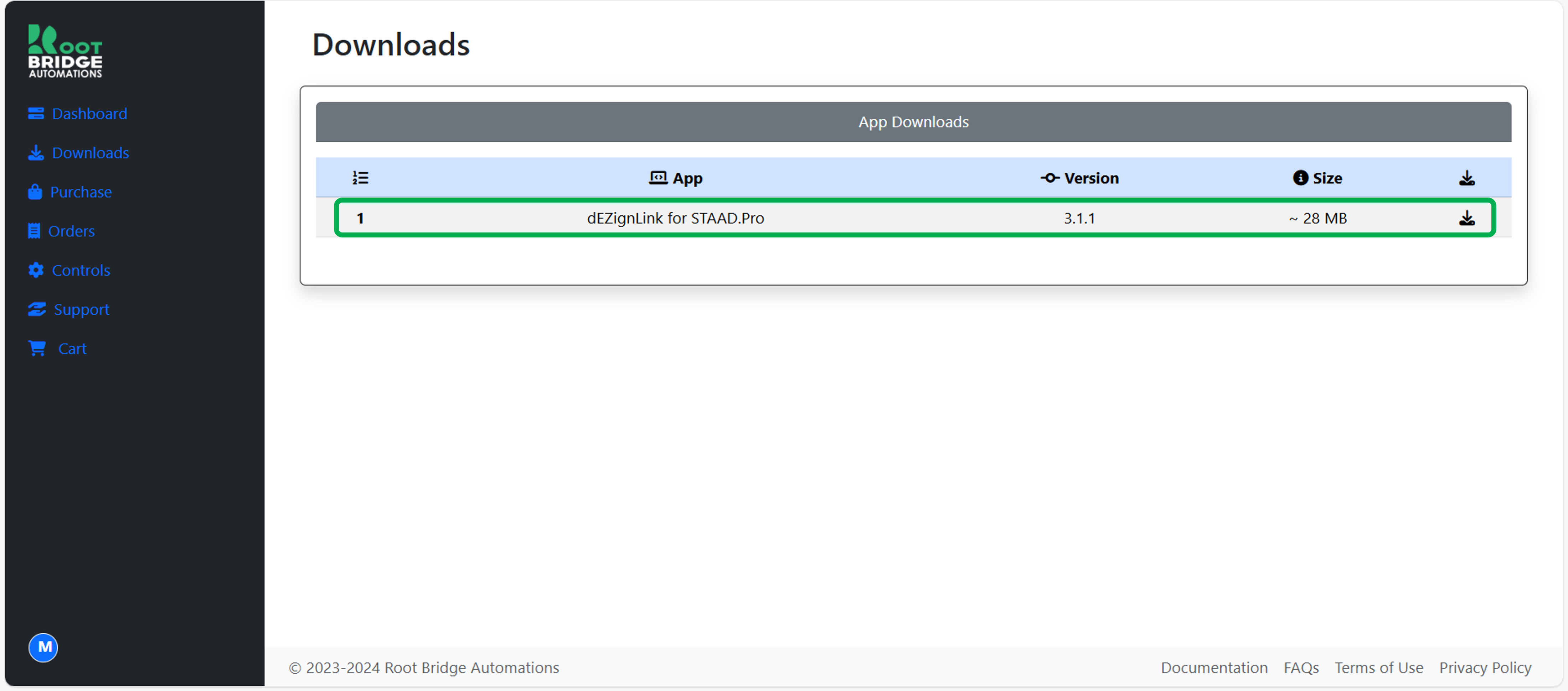
WARNING: Installer package obtained from any other source must not be used.
Upon successful installation, shortcuts will be created in the Desktop as well as the Start Menu.
GUI Log In
After launching the tool, you need to Log In first to start using the tool.
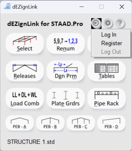
- Begin by clicking the "Log In" button as shown below:
- A window will popup as shown below. Enter the same login credentials that you used to register in our website.
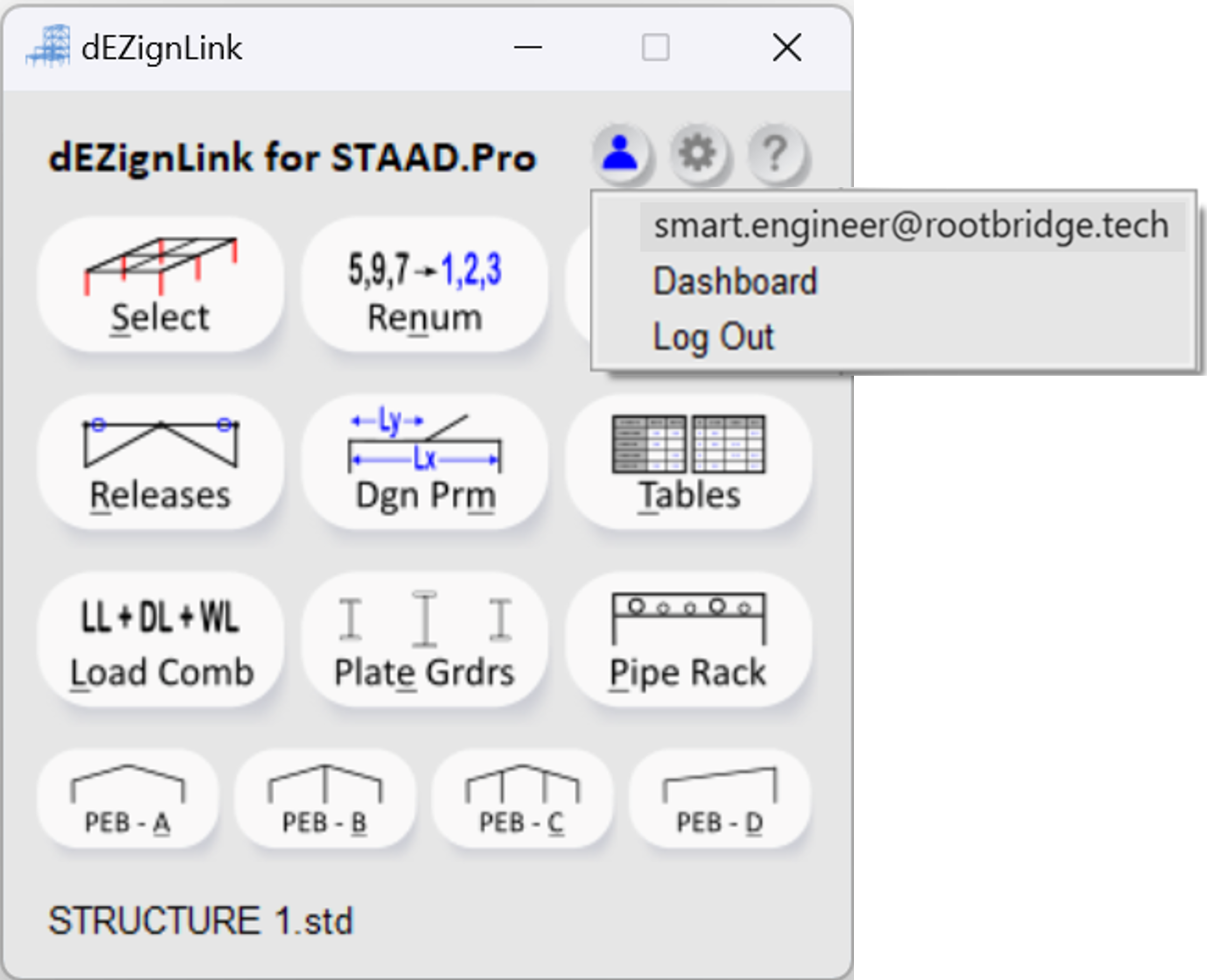
- Click on the "Submit" button. Once your login is successful, the Log In button on the tool shall change as shown below:
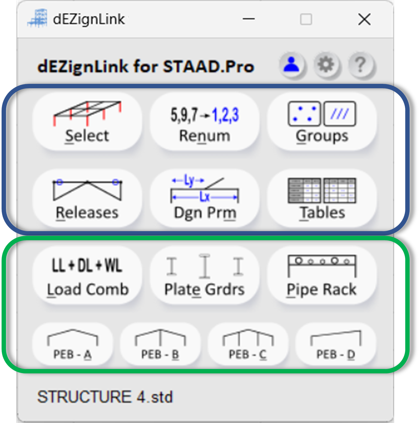
- Now you can use the tool. Availability of the functions shall depend upon your subscription validity. As shown below, the six tools at the top are free to use during the trial period. To continue using them after the trial, a subscription is required. All other tools remain free forever.
- The file name of the connected STAAD model is displayed at the bottom of the tool.
Info
The session lifetime is of 30 days, after which you will have to login again.
Select Members
 Keyboard shortcut: Alt+S
This tool allows you to select various structural elements with a single click.
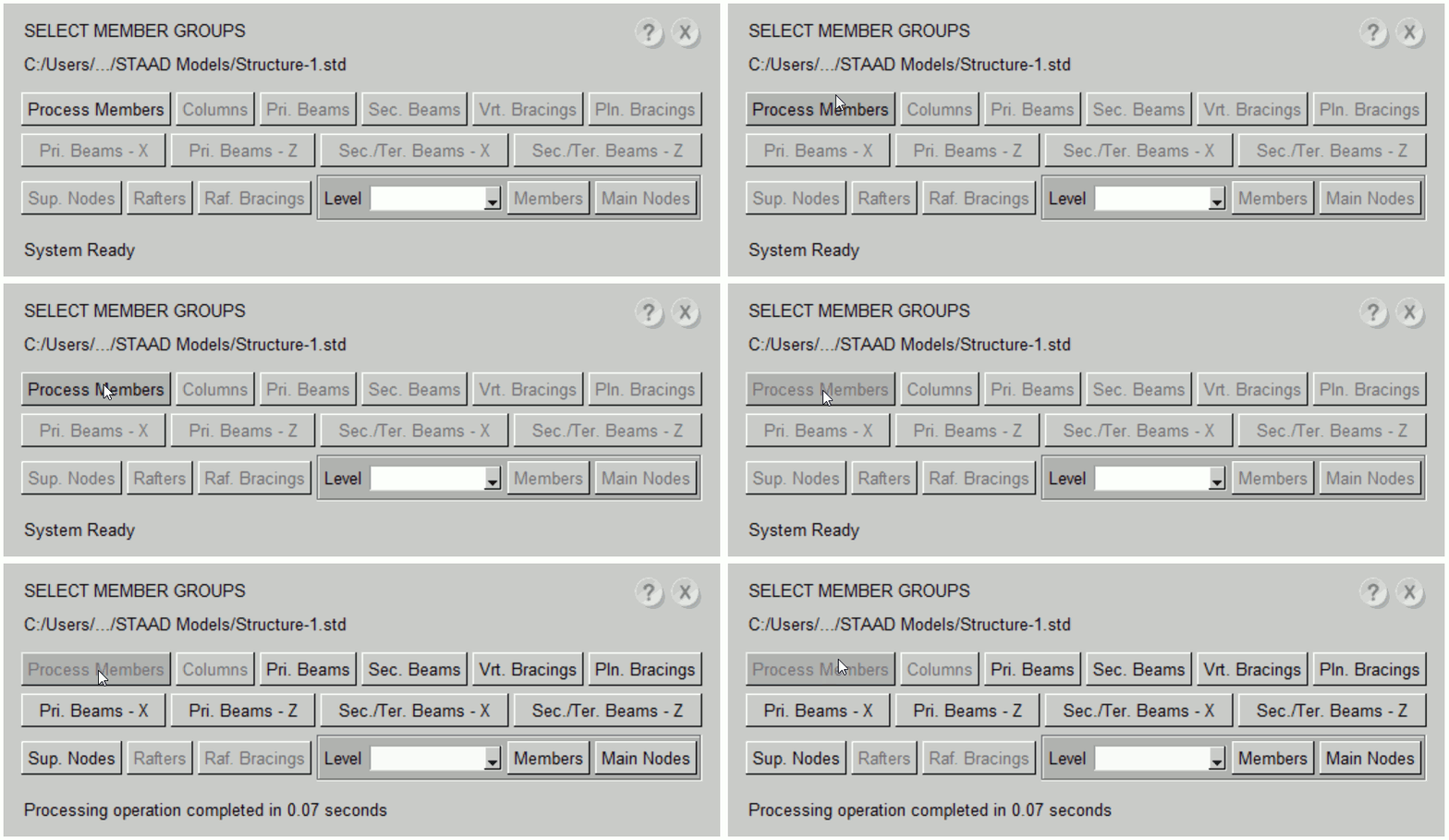
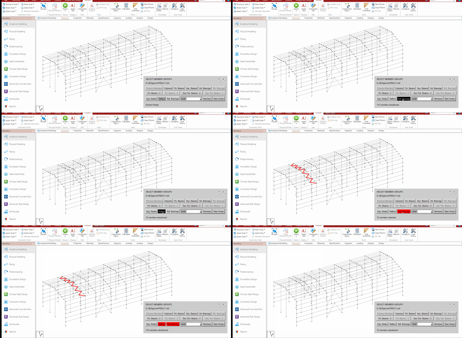
- Begin by clicking the "Process Members" button. This process may take a few seconds. Once completed, all other selection buttons will be activated.
- Some buttons in the SELECT tool shall remain inactive if the corresponding elements are not present in the current STAAD model. For example, if Vertical Bracings are absent in the model, the "Vrt. Bracings" button will not be activated.
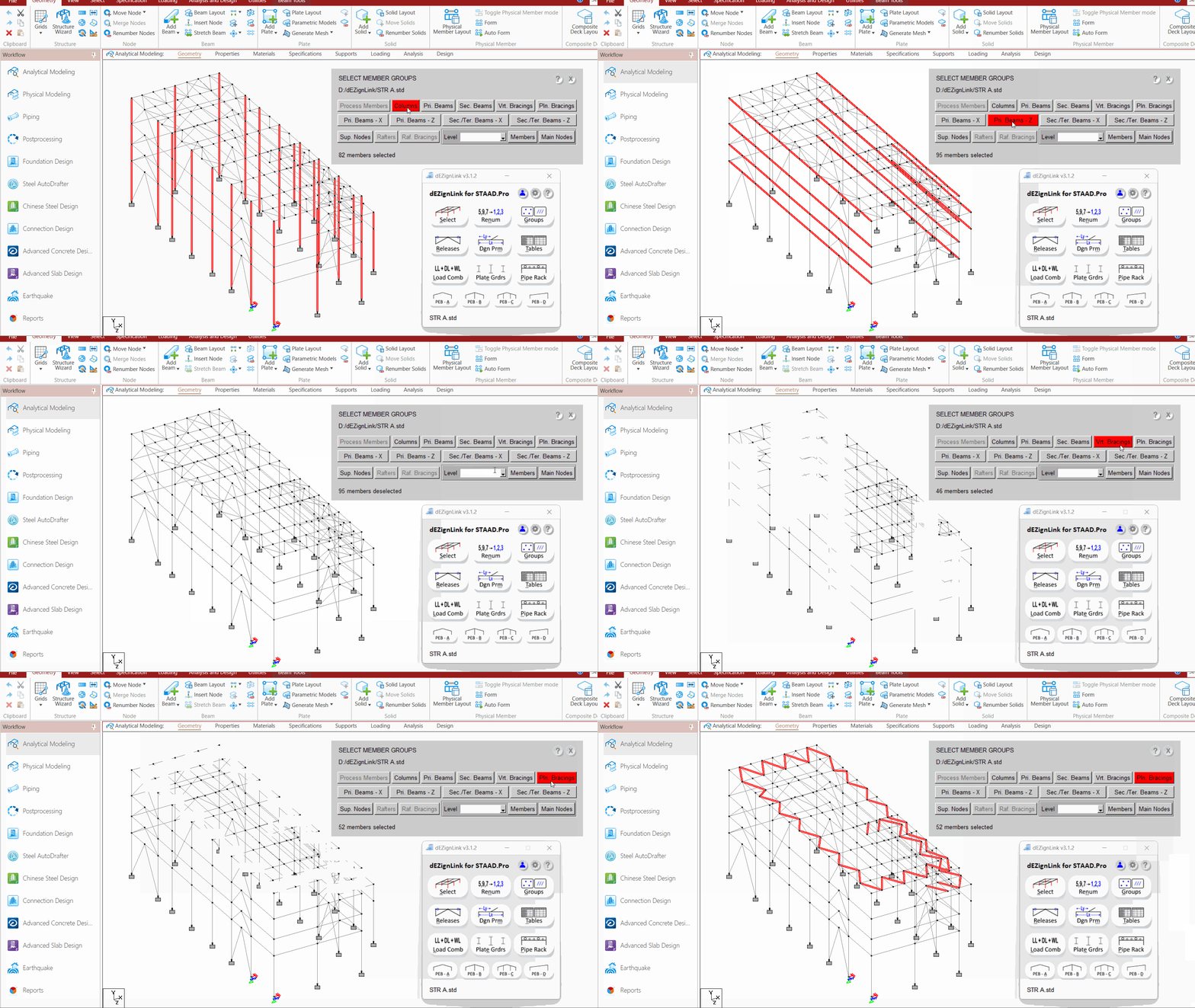
- You can now select the required elements from your model by clicking the corresponding buttons. For example, clicking "Pri. Beams - Z" will select all primary beams in the current model that are parallel to the Global Z direction. (Here, primary beams refer to beams connected from column to column.)
- Similarly, you can select Vertical or Plan bracings by clicking their respective buttons.
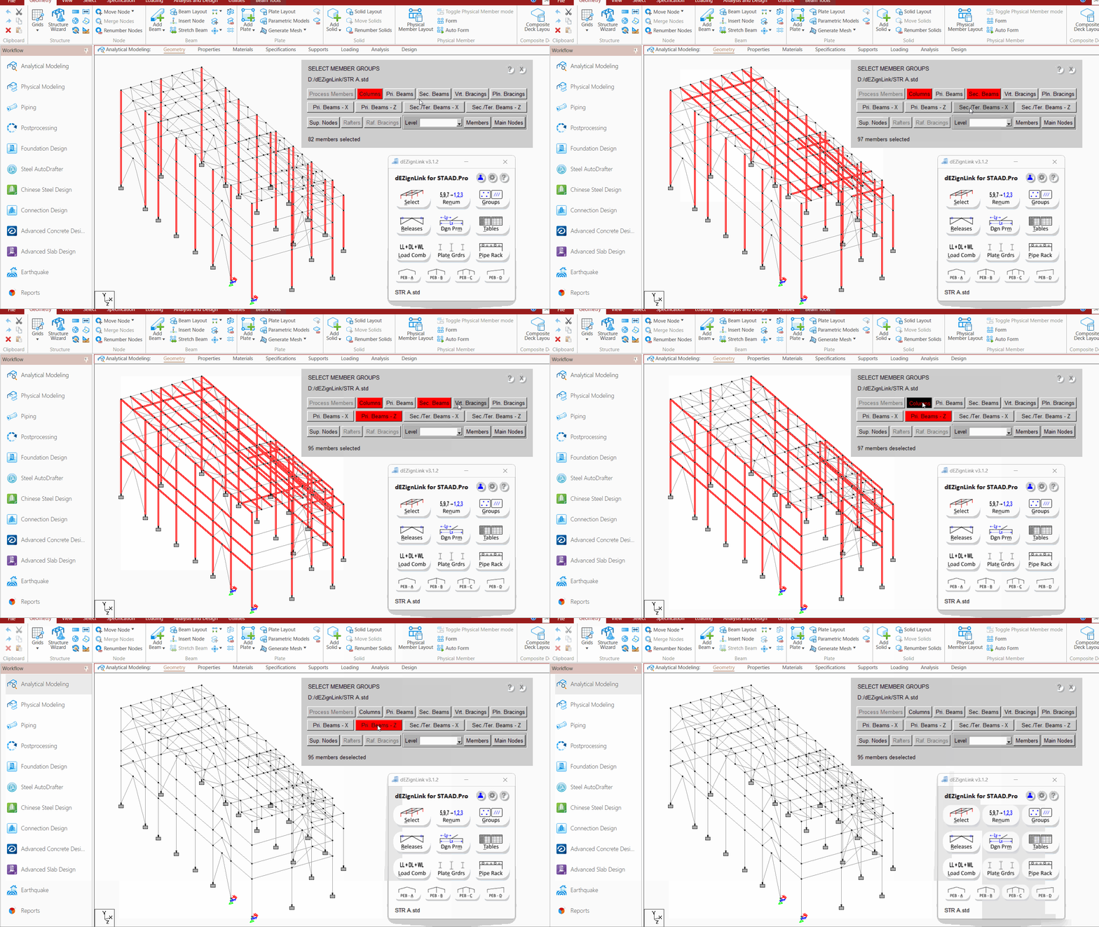
- Multiple selection buttons can be activated at the same time. When a button is selected, it will turn red. To deselect an item, click the button again; it will revert to its original colour.
- Note: If you click in the graphics window at any point, your entire selection will be cleared, although the buttons will remain red.
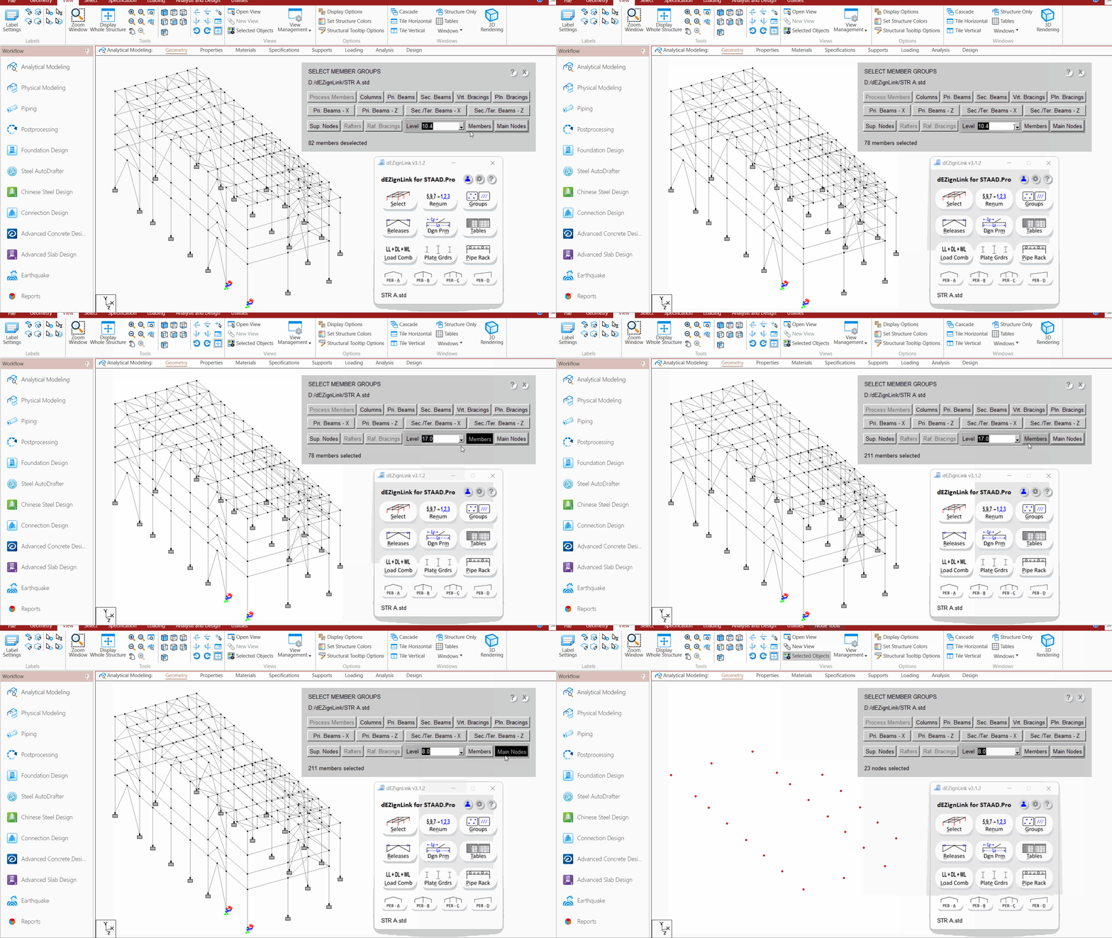
- For the "Level" drop down menu, choose the desired level (automatically extracted from the model) and press the "Members" or "Main Nodes" button as needed.
- Note: There are many nodes at particular level. We are generally interested in selecting Column Nodes only at each level for deflection checks and other such important functions. Here, Main Nodes refers to nodes lying on the columns.
- The buttons for "Rafters" or "Rafter Bracings" will be active only if they are present in the current model.
- In this context, Rafters refer to the inclined roof beams (primary beams) that connect the columns. Rafter bracings are the Plan bracings located within the inclined roof plane.
- If you make any geometrical changes in the model, you must press PROCESS MEMBERS again to use the SELECT Tool.
Check our video guide on Select Members
Renumbering
 Keyboard shortcut: Alt+N
This tool effortlessly renumbers large structures with a single click.
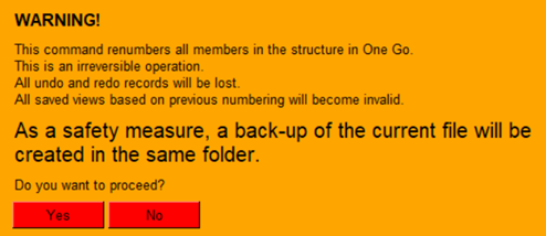
- Begin by clicking the "Renum" button. It will pop-up the following dialogue.
- Click "Yes" to proceed.
- The tool will automatically categorize elements such as Floor beams, Columns, and Bracings, and assign sequential numbering.
- For example,
-
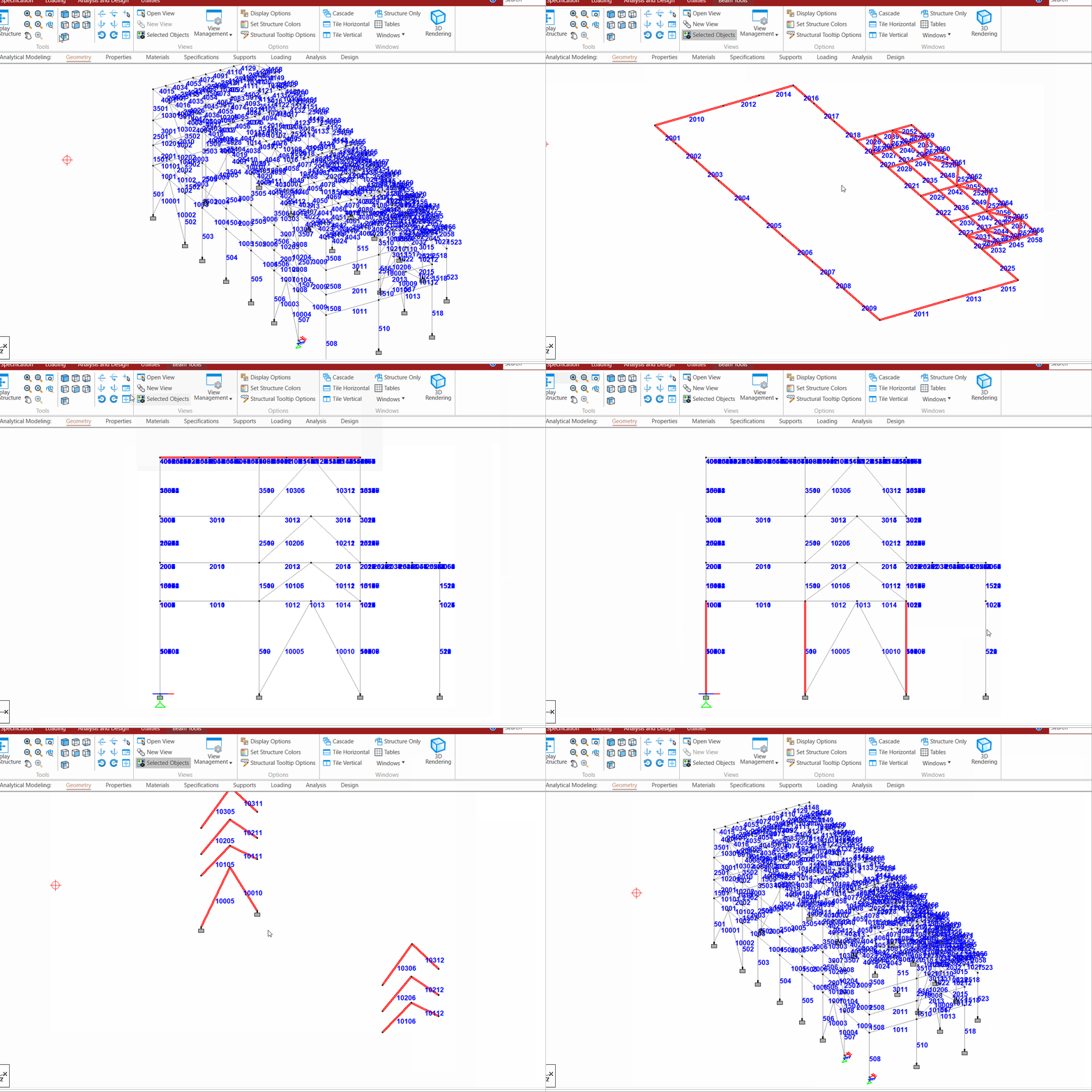
- The first floor beams will be numbered starting from 101 or 1001, while the second floor will begin from 201 or 2001, and so on.
- Columns will be numbered starting from 1501, with subsequent floors following at 2501, etc.
- Bracings will also be renumbered in a similar sequential pattern.
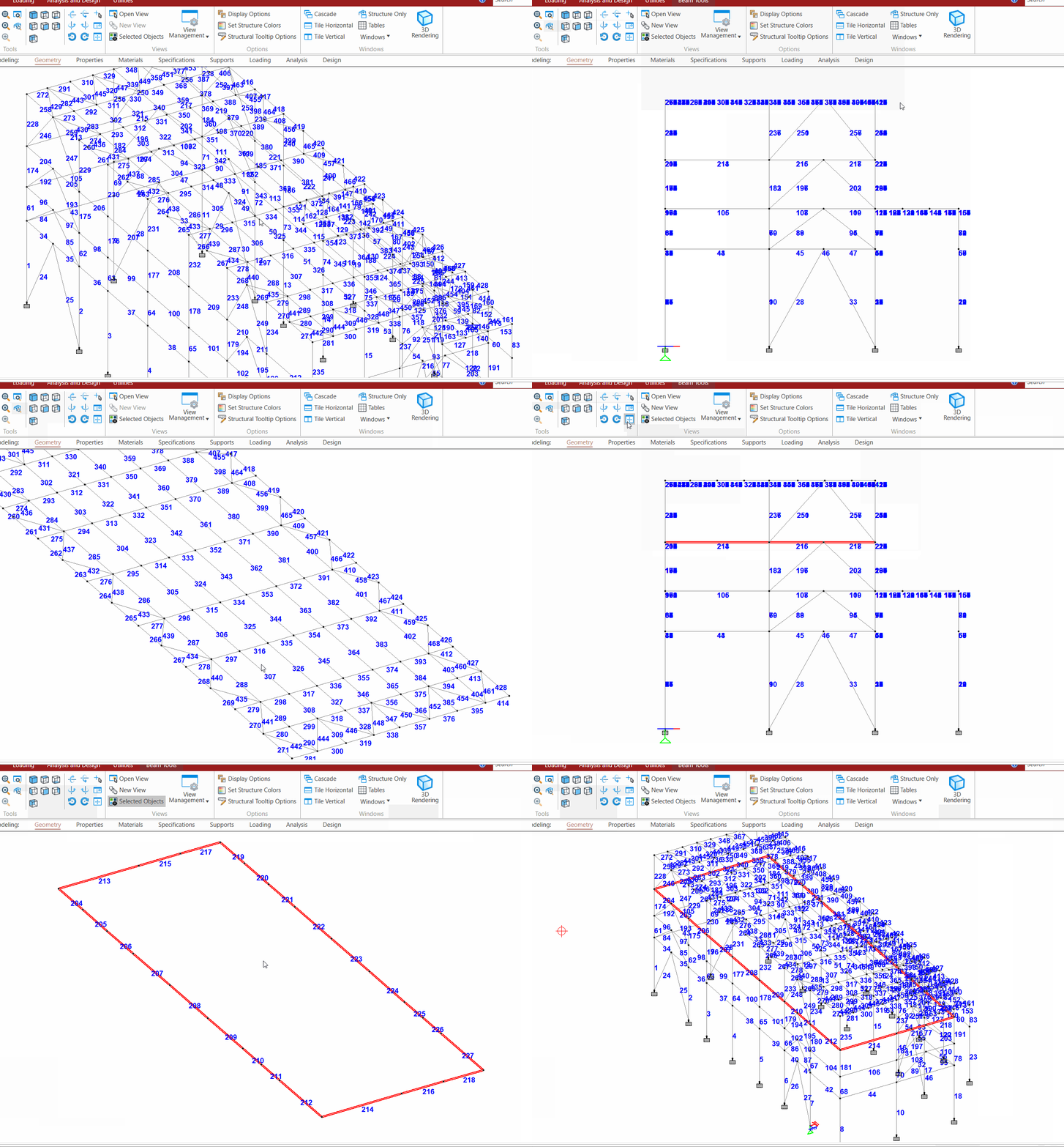
- Before Renumbering:
- After Renumbering:
- As a safety measure, a backup of the current file before renumbering is created in the same folder as the original.
Check our video guide on Renumbering
Define Groups
 Keyboard shortcut: Alt+G
You can create multiple predefined groups for the entire structure by simply pressing this button.
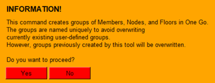
- Begin by clicking the "Groups" button. It will pop-up the following dialogue.
- Click "Yes" to proceed.
- The software will automatically generate many useful groups such as Main Beams, Secondary Beams, Floor wise Beams, Columns, Bracings, and more.
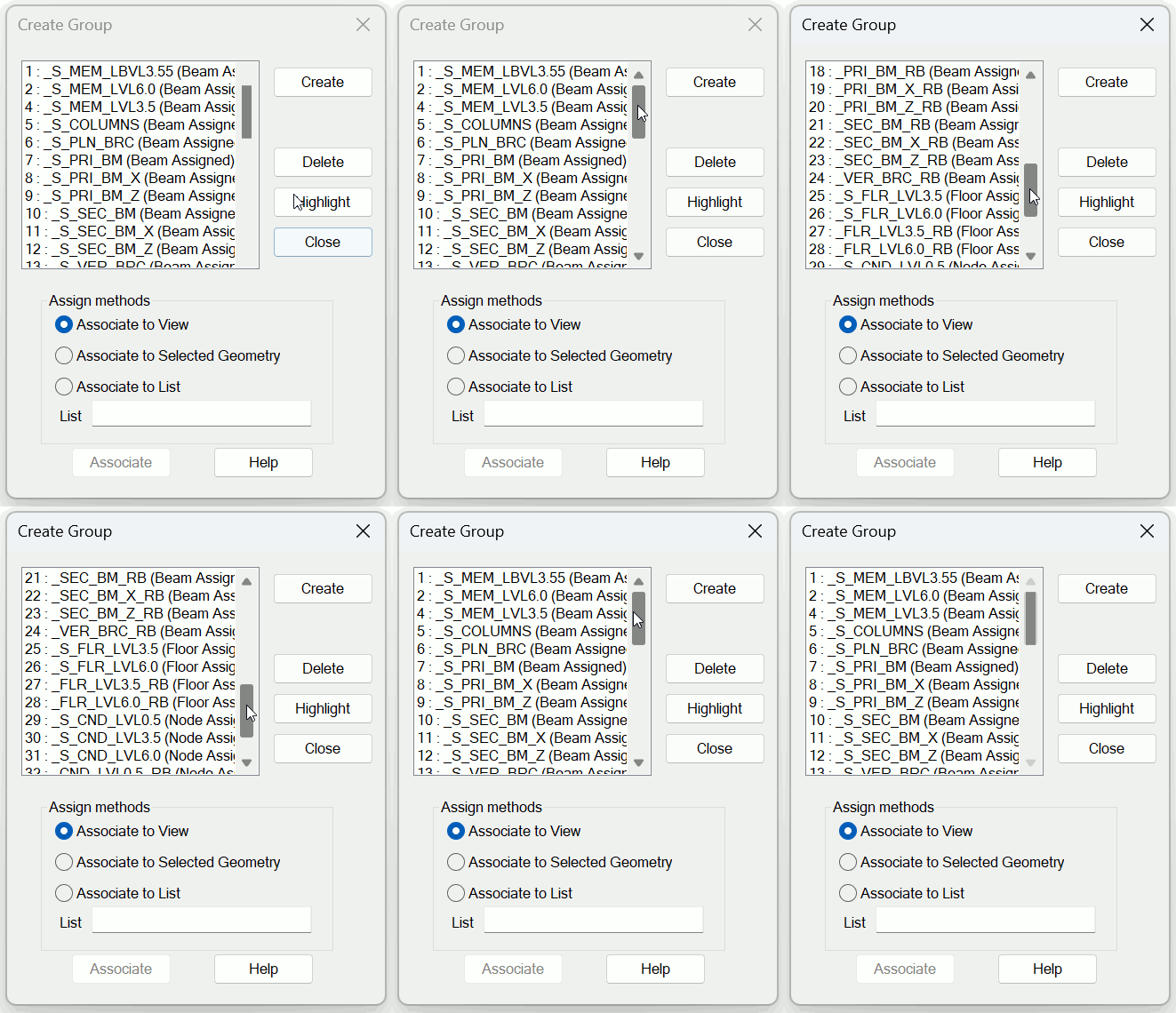
- The groups are named uniquely to avoid overwriting currently existing user-defined groups. The same can be accessed from STAAD.Pro > Utilities > Groups as shown below.
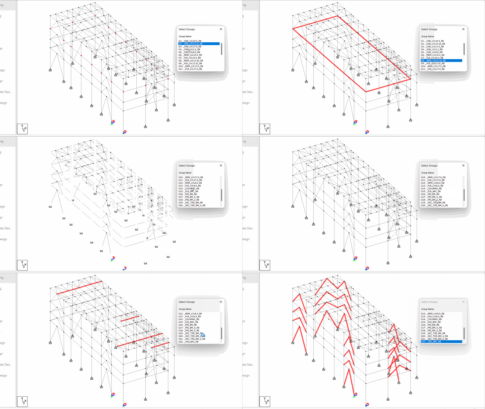
- The created groups can be selected as shown below:
- However, the groups previously created by this tool, if any, shall be overwritten.
Check our video guide on Define Groups
The Legend used by the tool for creating GROUPS is as follows:
| Group Nomenclature | Member Types in Group |
|---|---|
CND |
Column Nodes |
MEM |
Members |
FLR |
Floor groups for One way - Two way loading |
PLN_BRC |
All Plan Bracings |
PRI_BM |
All Primary Beams |
SEC_TER_BM |
All Secondary & Tertiary Beams |
VER_BRC |
All Vertical Bracings |
Define Releases
 Keyboard shortcut: Alt+R
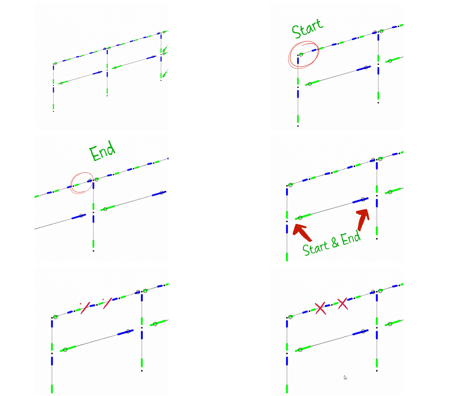
You can assign Releases (both START and END) simultaneously with this tool.
- Select all beams for which you want to define the same type of release. (Here you can use our SELECT toolbar to accelerate your work).
- Click the "Releases" button from the Main Toolbar. This will open a window as shown below.
- Click "Process Members" once to activate the "Define Releases" button.
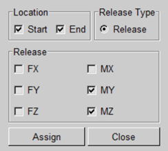
- Next, click the "Define Releases" button, which will open the following window.
- In this window, both START and END releases are selected by default. Choose the type of release you wish to assign (For e.g. MY & MZ).
- Thereafter, click "Assign" and that's it!. The tool is designed to intelligently detect the connection location requirements for most cases. It will automatically assign releases to the:
- start only,
- end only,
- both, or
- none,
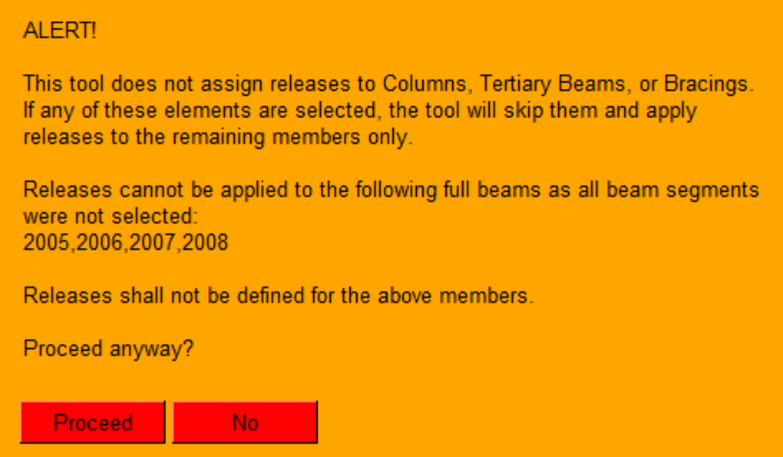
- This tool works for Primary and Secondary Beams only. If your selection contains any Columns, Bracings or, Tertiary Beams, it will show pop-up the ALERT as shown below. Also, Primary / Secondary beams whose all beam segments were not selected shall be ignored as indicated in the ALERT. In such case, you can click "Proceed" which will ignore the invalid type of members or incomplete selections of Primary/Secondary beams and complete the task.
Check our video guide on Releases
Design Parameters Generator
 Keyboard shortcut: Alt+M
You can assign Design Parameters in compliance to various codes, with just a few clicks through this tool.
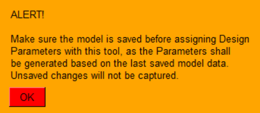
- To start with, click the "Dgn Prm" button. It will pop-up an alert as shown below.
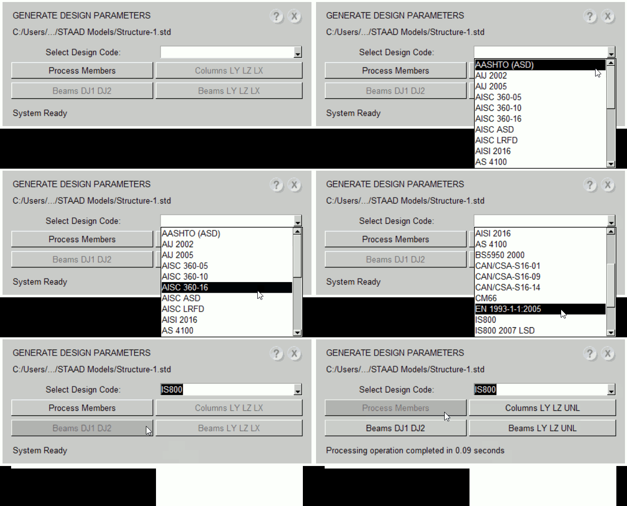
- Click "OK" to proceed. It will open a window as shown below.
- There is no need to select individual members, in fact, no need to select anything.
- Select the desired code from the drop-down list of available codes, and click "Process Members".
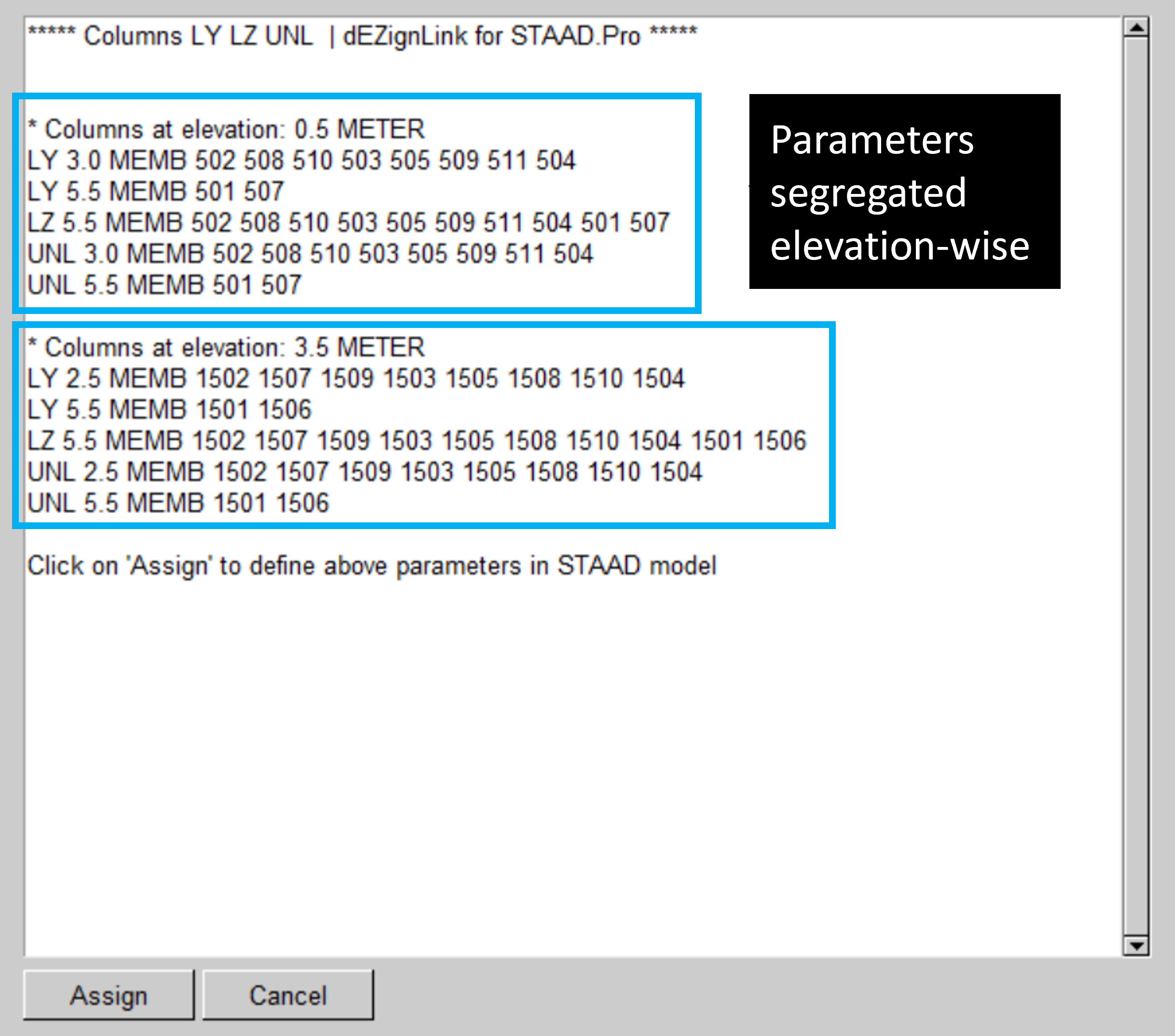
- This action will activate related buttons for design parameters - Effective Lengths for Columns, Effective Lengths for Beams and Deflection Joints.
- Click these three buttons one by one to get the required Design Parameters.
- This process will not only define each parameter but also organize them with appropriate titles for each section.
- In order to directly apply the generated parameters to the current STAAD model, click "Assign", or copy the generated parameter and use it as needed.
Check our video guide on Design Parameters
Analysis Results Tables
 Keyboard shortcut: Alt+T
This tool provides you the Result outputs in an Excel table format, along with pivot table functionality, with just a few clicks.
- NOTE: This tool can be used only after completing the model analysis.
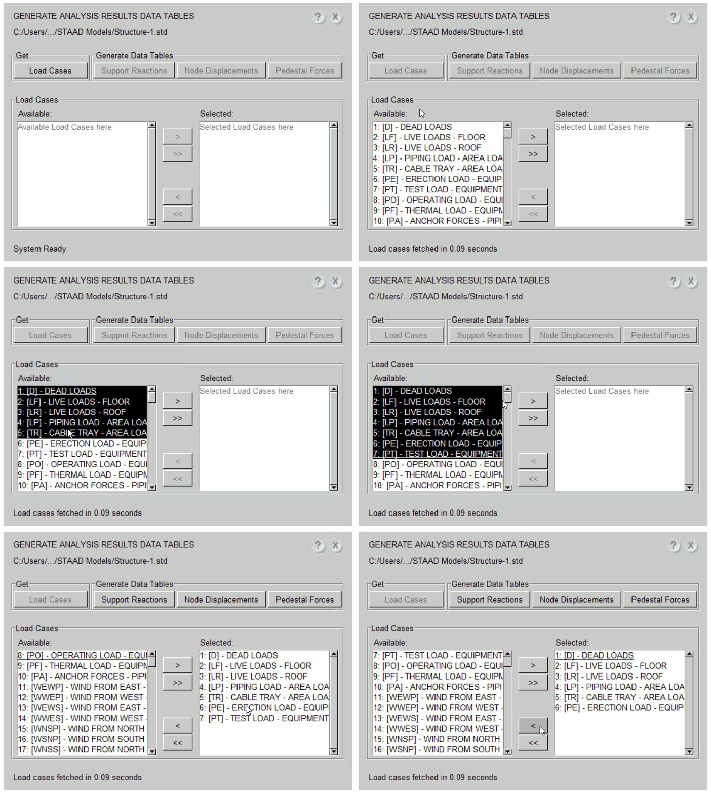
- Click the "Tables" button to open the window as shown below.
- Click "Load Cases" to display a list of Primary Load Cases and Load Combinations defined in your model.
- Select the required Load Cases or Load Combinations.
- Press one of three output buttons for the specific Output Table you need.
-
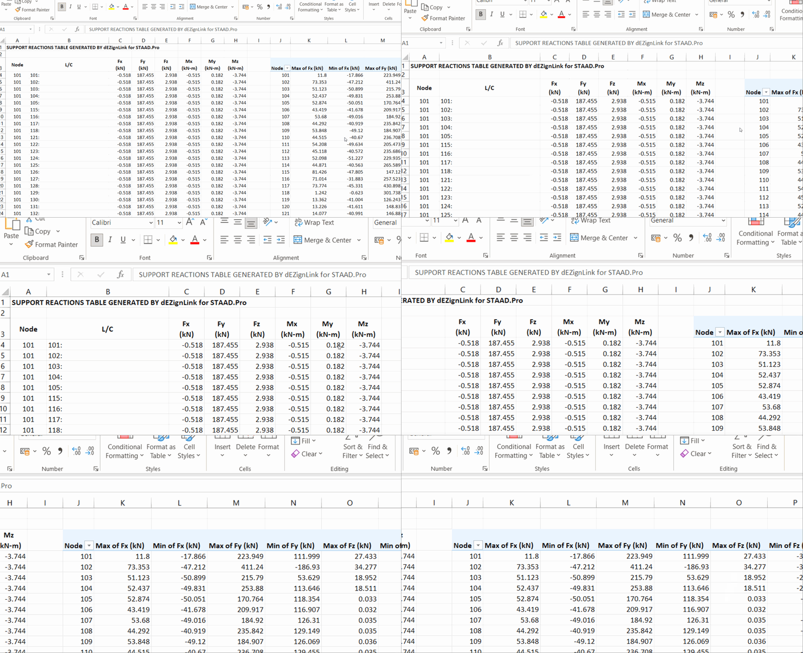
- Support Reactions: This option provides an Excel file showcasing Support Reactions, with an accompanying pivot table for a clearer overview, depicting Maximum and Minimum values, as shown in the example below.
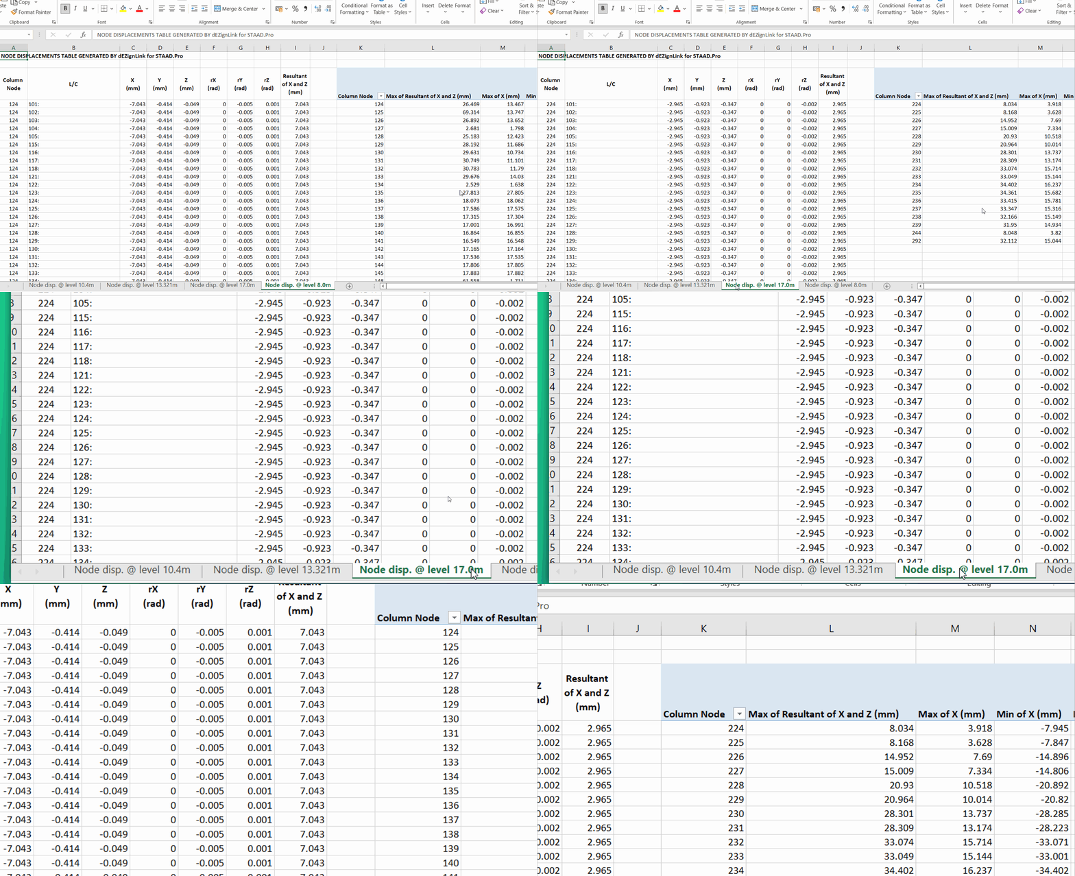
- Node Displacements: This feature creates an Excel file that organizes different floor levels into separate worksheets, generates Pivot tables for each level, and displays the maximum resultant displacement—all in one step. A sample screenshot is shown below.
- Pedestal Forces:
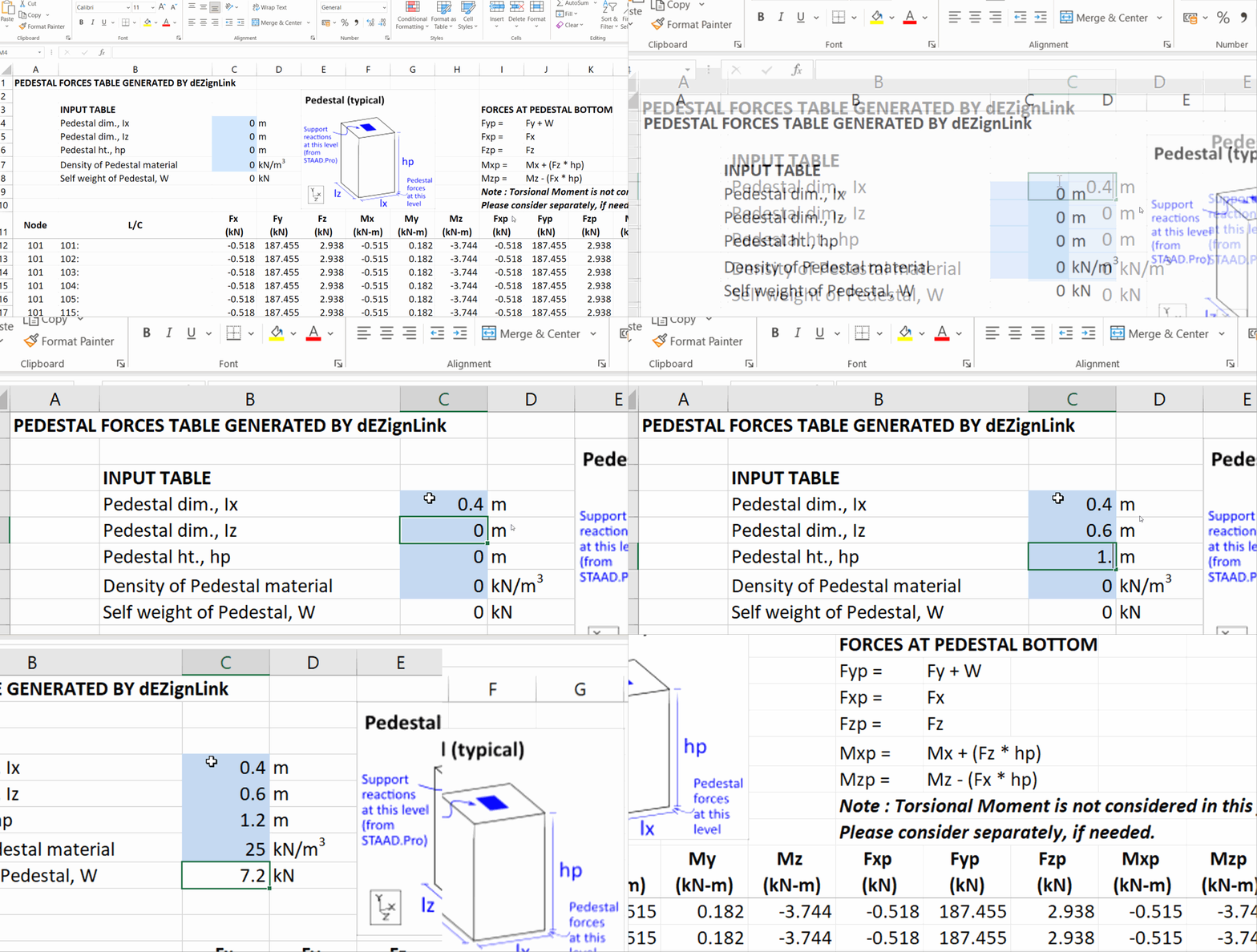
- This tool auto-calculates the forces required for Pedestal design. The generated Excel file allows you to input specific Pedestal parameters, such as dimensions, height and density, and outputs the necessary Design forces.
- It calculates moments by multiplying Horizontal Reactions (Fx, Fz) with height and calculates vertical forces by adding the self-weight to the Vertical reactions, providing Final Design Forces and Moments at the critical bottom section of the pedestal.
- This is particularly useful for designing RCC Pedestals that support Steel structures where you have not modelled Pedestals.
- All outputs will be generated in spreadsheet format compatible with MS Excel, and saved at the default location: Desktop\dEZignLink for STAAD.Pro . You can change this path by clicking the Settings icon
at the top-right corner of the dEZignLink toolbar.
Check our video guide on Results Tables
Load Combinations Generator
 Keyboard shortcut: Alt+L
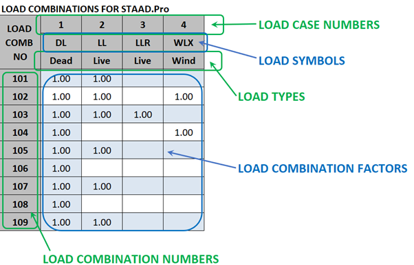
With this tool, you can generate a STAAD-compatible Load Combination file as well as a Load Case file effortlessly. Additionally, you can also get well-formatted tables for the same to use in your calculation reports.
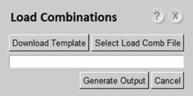
- Click the "Load Comb" button to open the window as shown below.
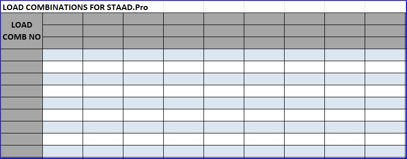
- Click the "Download Template" button to download the Microsift Excel compatible template for entering Load Combination data.
- Enter the Load Combination inputs in the downloaded template.
- Ensure that Load Case Numbers, Load Symbols, Load Types and Load Combination numbers are entered in the designated cells only, as shown in the screenshot below.
- Once you have completed entering all required data, save the template file at your preferred location.
- Click "Select Load Comb File" in the window and select the path of your filled in template file.
- Click "Generate Output" to create the output file.
- This tool will generate a Word file with the following content:
-
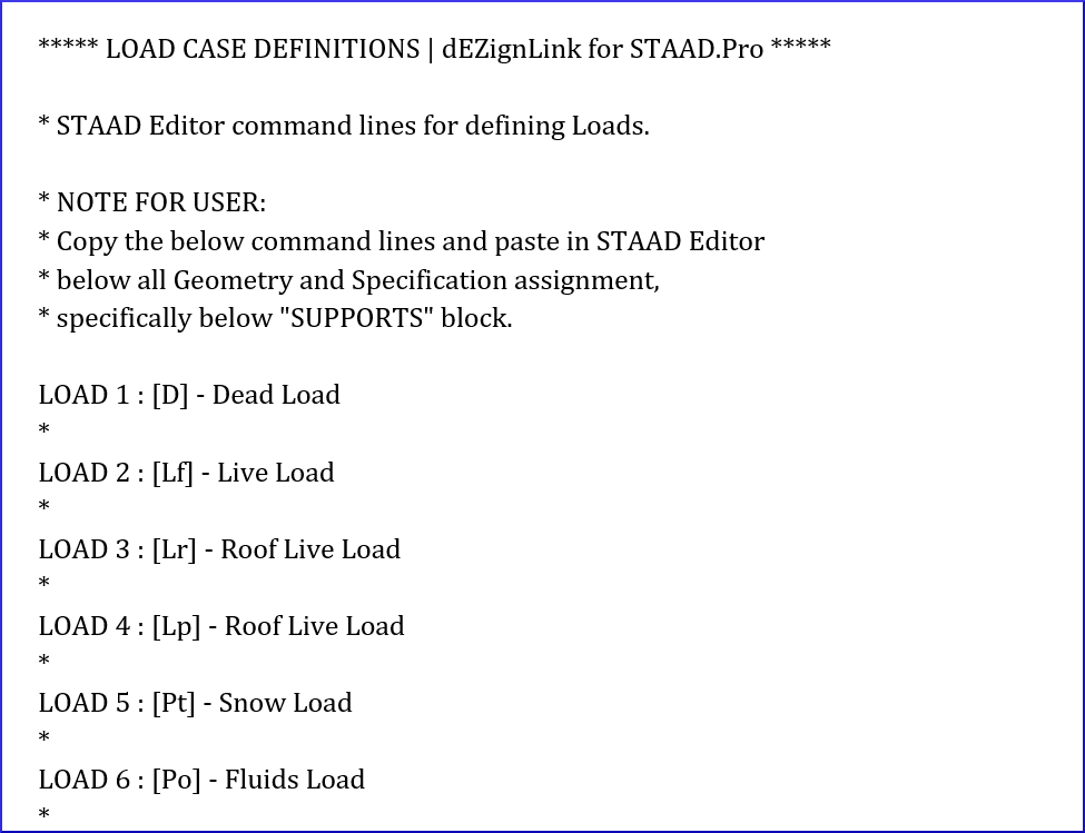
- STAAD.Pro compatible Load Case script, ready for use in the STAAD Editor.
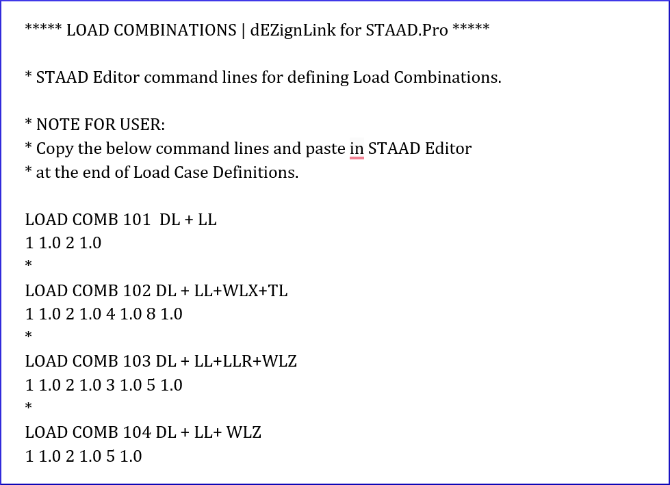
- STAAD.Pro compatible Load Combination script, ready for use in the STAAD Editor.
- Well-formatted tables for Load Cases that can be copied into your calculation reports.

- Well-formatted tables for Load Combinations that can be copied into your calculation reports.
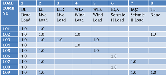
-
Check our video guide on Load Combinations
Custom Plate Girders
 Keyboard shortcut: Alt+E
With just one click, you can access multiple pre-defined I-section plate girders, ready for use.
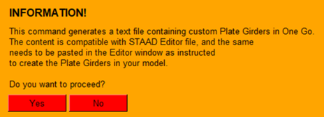
- Click the "Plate Girders" button. An information window shall appear as shown below.
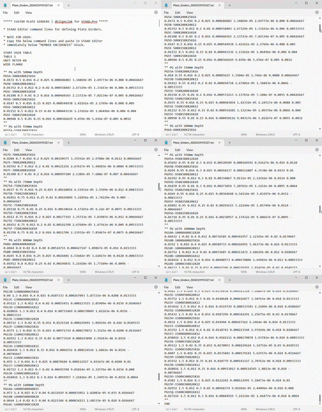
- Click "Yes" to proceed. This will create a text file containing a range of pre-defined plate girders.
- You can easily copy and incorporate these girders into any STAAD file as needed.
Check our video guide on Plate Girders
Pipe Rack and PEBs (Structure Wizards)


 Keyboard shortcuts: Alt+P, Alt+A, Alt+B, Alt+C, Alt+D respectively
Create geometry for Pipe Racks or Pre-Engineered Buildings (PEB) with just a click.
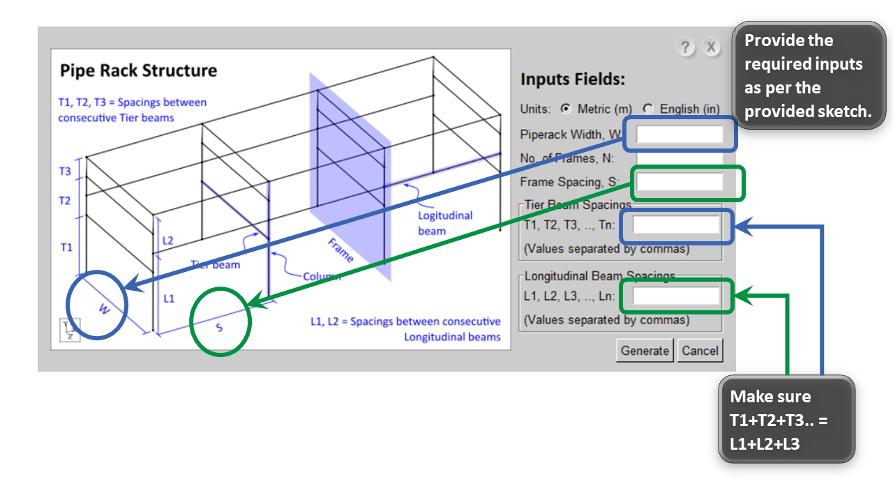
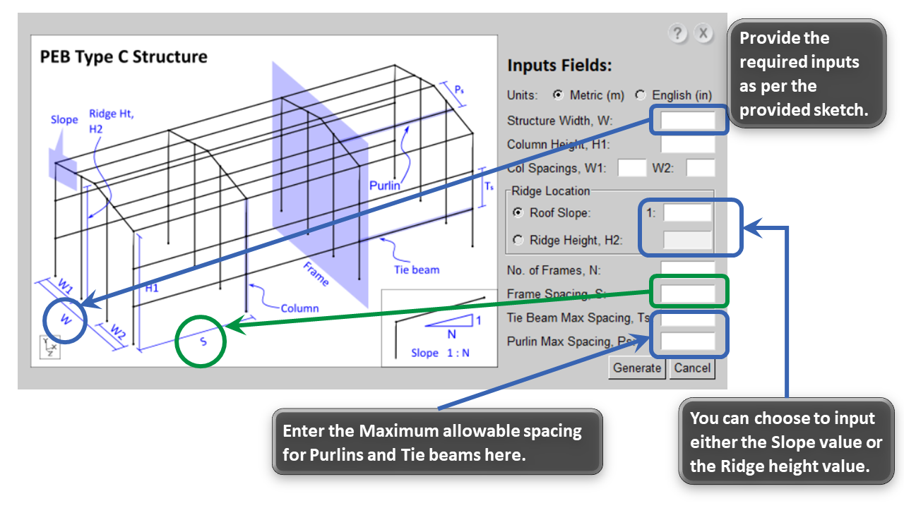
- Click on any button of your choice: "Pipe Rack", "PEB - A", "PEB - B", "PEB - C" or "PEB - D".
- Simply provide the required inputs in the corresponding dialog boxes, following the provided sketch.
- Click the "Generate" button.
- This will create a new STAAD file with the Geometry based on your specified input dimensions.
- You can select either Metric or English units according to your preference.
- Detailed information for sample Geometry Generators is provided below:
Check our video guide on Structure Wizards
Complete Video Guide
Check our complete video guide featuring all tools
Constraints and Recommendations
- STAAD Windows: Using two STAAD windows simultaneously while operating this tool is not recommended.
- Login Restrictions: If the tool is logged into a new workstation, the session on the previous workstation will automatically be logged out.
- Column Selection: When using the SELECT tool to select columns, stub columns are not included. This tool doesn't consider stub as Main columns.
- Secondary Beam Identification: If a beam is supported by a column on one side and a beam on the other, the tool classifies it as a secondary beam.
- Releases: Columns, Bracings and Truss members are not assigned releases by this tool.
- Knee Bracing: Contributions of knee bracings in reducing effective lengths are not considered. This aligns with common industry practices.
- Rafter Bracings vs. Plan Bracings: Bracings in inclined roofs are categorized as Rafter bracings and are not included in the plan bracing category.
- Renumbering Limitations: STAAD has a renumbering limit of 999,999 members. If this tool exceeds this limit, the user must manually re-assign numbers.
- Floor Groups Validation: The tool includes all members at a level (except bracings) in Floor groups. Adjust as needed to ensure that floor groups contain the members making closed geometry.
- Effective Length for Unsegmented Members: Effective lengths (LY, LZ, LX, etc.) are not defined for members with no intermediate nodes, as STAAD defaults to the full member length.
- Effective Length Decisions:
- Effective lengths (LY, LZ, LX, etc.) require Engineering judgment due to dependencies such as:
- The strength of the lateral restraining members.
- Linking of lateral restraining members with bracings.
- Whether the lateral restraining members are removable.
- This tool, by Default, assumes lateral restraining members which are modelled are sufficiently strong and braced too.
- Modify Design Parameters whenever required as per actual project scenario.
- Effective lengths (LY, LZ, LX, etc.) require Engineering judgment due to dependencies such as:
- Vertical Bracing Contribution: The tool does not account for the support provided by vertical bracings connected to the middle of a beam above when calculating DJ1 and DJ2 parameters for that beam. This aligns with common industry practices.
- Design Parameter Adjustments:
- Adjust design parameters manually for members with Beta angles other than 0°, 90°, 180° or 270°.
- Modify design parameters for members supported by trusses, cantilever beams, cantilever columns as required.
- Please note that this tool does not define design parameters for Rafters, Plan bracings, Vertical bracings or Truss members.
- General:
- Many features of this tool are not designed to handle structures with Curved members or Plate elements.
- The tool performs best with Regular and Orthogonal structures, delivering recommendable results in most cases.
- Users are advised to thoroughly review the outputs generated by this tool.
- The primary objective of this tool is to save substantial time by automating repetitive STAAD activities. Tasks that usually require hours can now be completed in seconds, allowing users to focus on more critical design aspects.
By understanding these limitations, users can better adapt their workflows and apply necessary manual adjustments wherever required.
System Compatibility
Our software is compatible with Windows 11 and STAAD.Pro CONNECT Edition. Users can verify compatibility with their specific Windows and STAAD.Pro versions during the free trial period.
